Abstract
Innovative products are recognized by designs which have creatively applied a new technology or when a common utilitarian product is been reinvented to reenergize its market appeal. This case study will describe the development of a unique medical device based on the interdependency of industrial design and plastics engineering to yield an award-winning design that could only be attained by a comprehensive integration of these two disciplines.
Introduction
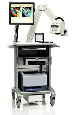
The design evolution and development of a state-of-the-art hand-held hyperspectral imaging camera began with industrial designers working with a small team of highly talented engineers to define the product embodiment. This medical device was the first of its kind to graphically map subcutaneous oxygenated blood distribution lying below skin tissue. Physicians would be provided invaluable data which could be directly correlated to skin tissue health and aid in the determination of wound healing.
This paper will review the design evolution starting with initial exploratory concepts, clinical research, plastics engineering development, simulation, testing, production liaison, and final production units. The synergistic benefits of seamlessly integrating industrial design with plastics engineering within a highly aggressive schedule will be emphasized.
A review of the selected concept and its transformation to a production medical device will be described based on compliance with numerous design parameters. Decisions for plastic material selection, process selection, ergonomics, aesthetics and numerous performance requirements will be covered. In addition, discussions pertaining to plastic part design based on considerations for molding and processing will also be included. The paper will also include a brief overview of considerations pertaining to DFM, hardware selection and choice of adhesives.
This paper is intended to demonstrate the benefits of integrating industrial design and plastics engineering within a highly efficient compressed development program. Readers will appreciate the importance of developing a product holistically versus the more conventional compartmentalized development process based on large teams of specialists within many disciplines.
Product Description and Function
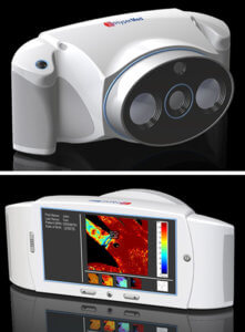
The Hyperview™ is the only handheld noninvasive oximeter available in the medical field today. Its purpose is to determine oxygenation levels beneath superficial tissue for patients with potential circulatory compromise. It’s a completely noninvasive tissue oxygenation measurement system that reports the approximate values of oxygen saturation oxyhemoglobin levels and deoxyhemoglobin levels in the subcutaneous venial system. Initial applications for this device were targeted for diabetic patients suffering from poor circulatory conditions and extremities such as feet. Since its introduction approximately two years ago it has been recognized as an indispensable for analyzing skin tissue in cancer patients, burn victims, plastic surgery patients and many other applications.
Initial Research Phase and Product Specifications
This project is a classic example of integrated design seamlessly integrating industrial design with plastics engineering to achieve a design which would not have been possible if it was developed in a traditional approach. Transformation of a large cart-based scanner into a handheld device required an extensive amount of research.
All team members were introduced to the product, its function, user interface, components and fundamental technology. In addition to the aforementioned, the industrial design, product development team began to document critical human factors considerations, marketing requirements, user requirements and aesthetic possibilities for the new device. As the project evolved a comprehensive product specification document was compiled defining all the major product design requirements including software user interface, electrical components, optics, including lenses and illumination, environments of use, regulatory requirements and hundreds of other parameters. It should be noted that a significant portion of this document was dedicated to mechanical performance including drop tests, chemical resistance, UV stability, colors, ease of cleaning and rigidity. These parameters would eventually provide guidance for plastic material selection later in the project.
These specifications were essential for the development team to map out the overall size and shape of the product, internal component arrangements, locations of buttons and controls, the definition of information to be displayed as well as preliminary user-interface menus, material selection manufacturing processes, number of parts, and of course assembly and service considerations. It should be noted that these specifications were modified as the project progressed while also providing a consistent set of design objectives for the entire development team.
Concept Development and Evaluation
 As the research phase of the project approached its conclusion, the industrial design team began interpreting the information and examining numerous handheld products currently on the market for inspiration as well as identifying design trends. Preliminary block form studies were created based on the estimated size and number of components during the early stages of this project. These blocks were oriented in six different configurations based on three axes to determine which orientation was most suitable for the device.
They were presented to physicians and clinicians familiar with the existing cart-based system. These individuals were questioned for their feedback based on clinical use, patient interaction, storage and handling. These simple block forms were very helpful during the early stages of development. They enabled the industrial design team to identify ideal configurations and orientations for this completely new product which was setting a new precedent. It should be noted that materials and process options were not considered in any way during this very preliminary design phase.
Concept Refinement
 These concepts were eventually abandoned due to technical problems associated with user-interface size and poor perception of the overall appearance utilizing commercially available tablets or cell phones. As more information was accumulated and the components were more clearly defined, a viable design direct emerged.
The final concept was strategically modeled after a conventional SLR camera to provide users with a familiar metaphor, thus enhancing intuitive product use.
However, unlike a conventional SLR camera, the hyperspectral camera was designed with two ergonomically designed hand grips on either side. Although these handles were not originally included in the initial SLR camera concepts, they were added based on the increase in size and weight of the device as the design evolved. They became a necessary and challenging addition to the device because of their complex geometry. It should be noted that considerations for molding, assembly and tooling were included during this stage of development to maximize the efficient interpretation of the concept into a production product without loss of design intent. The next step was to translate the ergonomically, functionally and aesthetically approved design into a production product which complied with all the product specifications.

Plastics Engineering Development and Production Design
Defining Parts and Overall Assembly
It should be noted that the development of the final accepted concept into a production design was a seamless evolutionary process versus a completely independent development phase requiring extensive design iterations. During design development, the transition from one phase to another was essentially non-existent because many of the parameters associated with production design were resolved as the concept design was refined. The emphasis of work gradually shifted from factors most associated with the user and industrial design to those exclusively dedicated to functional and manufacturing parameters. During the plastics engineering phase of development, the majority the time shifted to detailing part geometry to comply with an optimization of the following:
- Maintaining aesthetic design intent
- Optimizing human factors
- Segmenting the overall form into parts which can be easily molded
- Segmenting the assembly into the minimum number of required parts
- Segmenting the overall form into parts within minimal seams for ease of cleaning
- Considerations for ease of assembly, testing and service
- Selecting optimum resins for each component
- Forecasting potential tolerance stack-ups and options
- Determining ideal assembly, design and materials to withstand 3-foot drop test into the concrete floor without damage
The primary objective was to maintain design intent without compromising any of the high priority product specifications listed above.
One of the most crucial steps during the transition of a concept into actual product design is deciding how the product will be segmented into individual parts. This decision will affect appearance, unit cost, assembly time, tooling cost and overall product reliability.
The architecture of the hyperspectral camera was based on a highly functional injection molded inner chassis and an outer three-piece protective shell. Mechanical and structural requirements for the inner chassis were extremely challenging since the plastic parts had to support a number of precision optical components and electronic sub-assemblies within a very densely packed volume. This requirement was fulfilled with a very simple concept which included two complexes, highly functional injection molded parts which satisfied all the functional requirements with the minimum part count. An extensive effort was also made to design the outer shell with the minimum number of parts to maximize structural integrity and minimize difficult to clean seams.
Process and Selection of Molder
After the basic architecture of the device was defined and verified, our team focused attention on the challenges associated with the main out shell which included two thick handles attached to either side of the camera body as previously mentioned. Three possible design options were considered:
- Two sets of injection molded two-piece handle sub-assembled and fastened to the main body
- Injection molded body with half a handle on either side which would be fastened to mating injection molded opposite side with screws
- One-piece integral body and handles on either side
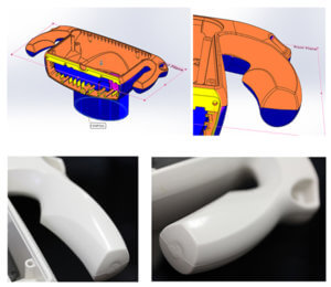 Although the last option was the most attractive, it presented technical many challenges related to ease of molding, process selection and identifying the ideal molder. Since the benefits of a single integral part were so significant, three processes were investigated; structural foam, gas counter pressure and gas assist injection molding. After discussions with two of the top structural foam molders in the US, it became immediately apparent that this process would not be appropriate. Painting, rough surface finish and limited rendition of fine details eliminated this process from the list. Although gas counterpressure molding would have provided a smoother surface, complex part geometry raised may doubt about the viability of this process. The last option, gas assist injection, remained the best choice, however complex geometry and the limited number of credible molders introduced additional concerns. In-depth interviews with a select group of molders confirmed gas assist to be the best process choice and eventually enabled us to select the best molder for this project, Mack Molding in Arlington Vermont.
Part Detailing: Designing for Each Process
After this critical decision was made, the design team began the tedious task of detailing all the parts with appropriate draft angles, wall thicknesses and features required to maintain the design intent while also complying with considerations for tooling and injection molding. It should be noted that a project of this complexity required constant communication with the molder to ensure the design features could be attained. Since the same molder was assigned the task of molding all the plastic parts, risks, management and assignment of responsibilities associated with multiple vendors were eliminated.
The internal chassis and many smaller parts were detailed for conventional injection molding. The main housing was detailed for gas assist injection and the front camera lens bezel plus the rear LCD display cover were designed for two shot over-molding. Three different injection molding processes were required to mold all the parts. The entire inner chassis was designed as a fully functional sub-assembly which was inserted into the rear of the camera housing. A specially designed one-piece elastomeric suspension system was designed to securely isolate the internal optoelectronic engine from the outer shell. The entire assembly was literally supported within an elastomeric membrane surrounded by an external hard protective shell and restrained by compressing the entire assembly with a thin stainless-steel frame. This unconventional design isolated the fragile internal components from the external frame, allowing the unit to be dropped onto hard surfaces without transferring severe shock loads to the internal parts.
Material Specification and Plastics Engineering
Selection of optimum plastic materials was another critical design decision which had to be determined before CAD files were released for tooling. Specifications for plastics were determined before CAD files were released for tooling because of varying shrinkage rates of different materials, melt index and gate designs.
Plastic selection for medical devices is always challenging and extremely critical. This complex device requires numerous materials based on different functional requirements. The external housing for example required material to comply with the following specifications:
- Color matching
- Ease of bonding
- Resistant to harsh disinfectants
- Easily molded for tight tolerances
- Impact resistant
- Easily pad printed
- High tensile strength
- UV resistant
- 94-V0
- High stiffness
- Easily commercially available
The number of polymers which complied with these general requirements was limited to less than 5. Of the tens of thousands of plastics, the search was quickly narrowed down to polysiloxane/polycarbonate copolymer. Close associations with material suppliers and a comprehensive awareness of performance criteria provided the team with a comprehensive and highly efficient means of identifying the optimum resin. Other materials included in this application were 30% carbon filled polycarbonate for the internal chassis, EPDM for elastomeric components and co-polyesters for clear lenses.
Design Finalization and Analysis
Design challenges associated with injection molding always converge at a few basic design parameters. These include the inclusion of draft, radii, maintaining correct wall thicknesses to avoid sink marks, accounting for proper material flow, avoidance of undercuts and always being aware of tolerance stack-ups. Although these considerations are basic, an application within complex part geometries is always difficult and time-consuming. A relatively simple part is always complicated by orders of magnitude after these design parameters are added to the CAD geometry. In addition to accounting for all the molding and processing factors, every part was repeatedly checked for potential tolerance stack-ups and reasonable clearances.
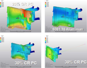 Dynamic FEA analyses were performed to evaluate the impact resistance of the system as well as effects of thermal expansion on critical optical components. An interesting thermal problem was uncovered after the first articles were molded and assembled. The following paragraphs will describe the problem, analysis and solution.
A pair of laser diodes were designed at either end of the optical chassis for easy alignment to converge at a common point at a specific distance from the target, thus establishing the proper focal distance for the camera. Testing of the first fully assembled molded units revealed a problem of the laser beams drifting apart from one another by as much as 12mm. The temperature rise was only 22 deg C and the chassis to which the lasers were mounted was originally specified in 30% glass reinforced polycarbonate with a modulus of approximately 6.6 GPa and a coefficient of thermal expansion of 21.6 um/m-C which is almost identical to aluminum. A tested aluminum chassis did not exhibit any drift under similar conditions. Thermal FEA studies of the various plastic versus aluminum chassis revealed the difference in modulus had a greater affect on expansion than CTE. The resin was changed from 30% GR-PC to 30% carbon filled PC and the problem was essentially eliminated. The higher modulus of 15 GPa and half the CTE of glass reinforced polycarbonate greatly improved performance
Conclusion of plastics engineering synergy with industrial design
Hopefully, this paper effectively described the interrelationships between industrial designers and engineers within a holistically managed design program. Furthermore, the final design was entirely dependent on the close interdependence of plastics engineering, plastics technology, and industrial design. The final product was recognized by the medic